
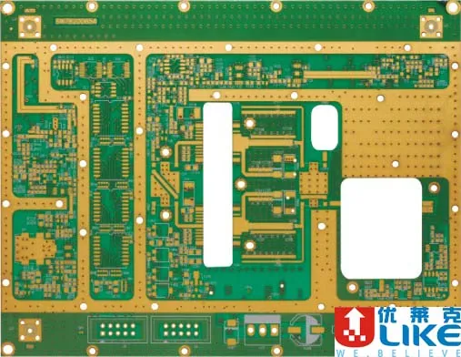
High-frequency PCB Board
High-frequency PCB Board is a ULIKE PCB engineering reference. It covers schematic review, PCB layout, stack-up planning, impedance-aware routing, manufacturability review, and engineering documentation.
Ask About Similar Projectsproject record
Process notes
- surface finishes: HASL, lead-free HASL, ENIG, full-board gold plating, connector gold plating, immersion tin/silver, OSP blue mask, and carbon ink
- 2-10 layer multilayer boards in volume, with small-batch 6-layer and 8-layer HDI support
- minimum line width / spacing: 3 mil / 3 mil; BGA pitch around 0.25 mm
- minimum finished hole diameter: 0.1 mm
- maximum board size: 610 mm x 1200 mm
- solder mask inks: Tamura and Taiyo photosensitive inks
DELIVERY CONTROL
Delivery attention
- Provide mechanical limits, connector positions and keep-out areas before layout starts.
- Confirm stack-up, impedance and key signal requirements early to reduce board revision.
- Before fabrication, review Gerber, drill, paste mask and assembly drawings together.
PROJECT RECORD
Project record
ULIKE used this PCB engineering case to support manufacturable layouts, clearer production documentation, faster prototype cycles, and smoother handoff into PCB or PCBA production. Key technical notes include: surface finishes: HASL, lead-free HASL, ENIG, full-board gold plating, connector gold plating, immersion tin/silver, OSP blue mask, and carbon ink; 2-10 layer multilayer boards in volume, with small-batch 6-layer and 8-layer HDI support; minimum line width / spacing: 3 mil / 3 mil; BGA pitch around 0.25 mm; minimum finished hole diameter: 0.1 mm.
The work is suitable for customers that need reliable engineering review, production control, quality verification, and delivery handoff.
PROJECT IMAGES
Image record
Photos are kept as production and project references.